| Item Name | Item Code |
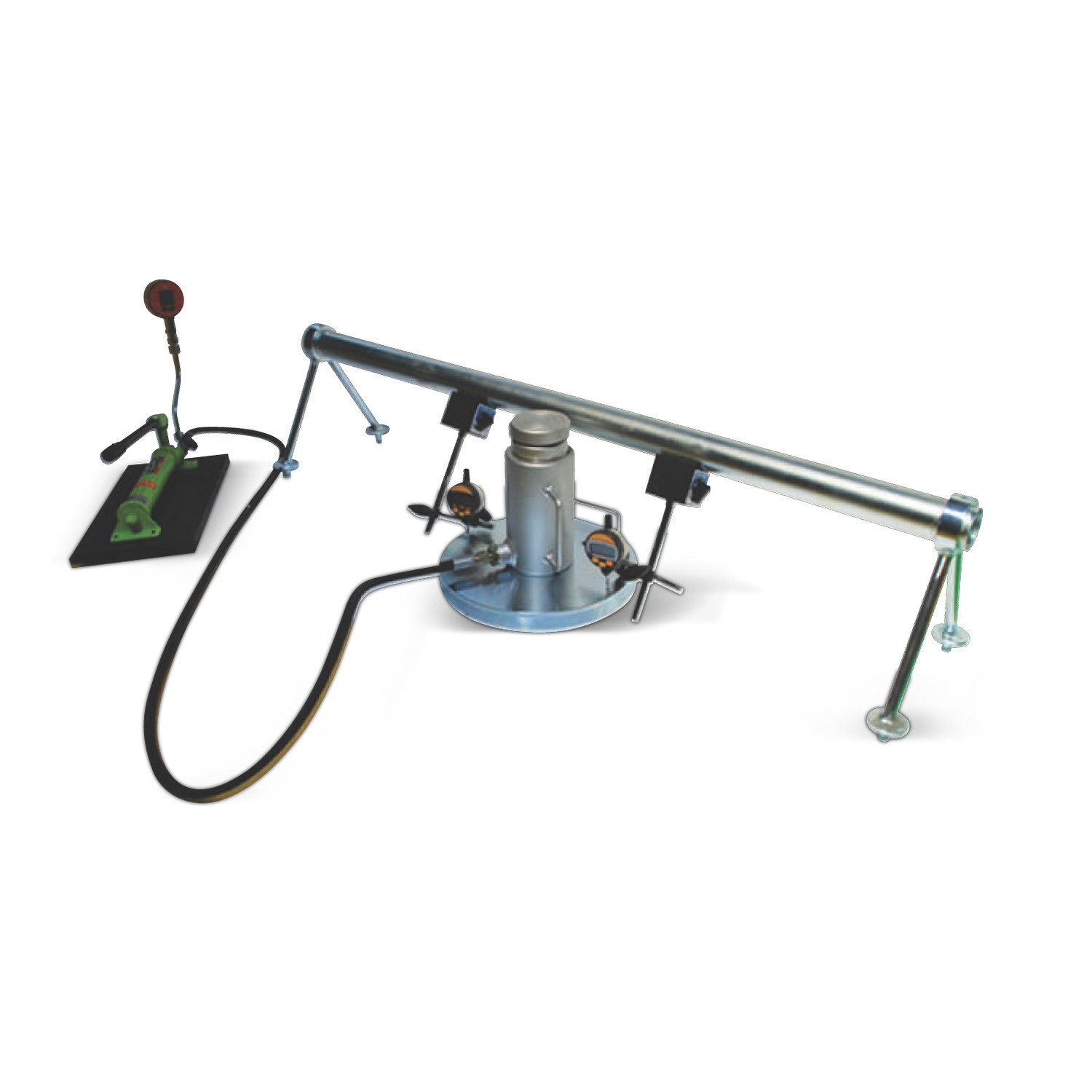
| PLATE LOAD TEST SET - 100 kN | T063H10XD |
| PLATE LOAD TEST SET - 250 kN | T063H25XD |
| PLATE LOAD TEST SET - 500 kN | T063H50XD |
| DATUM BAR for PLATE LOAD TEST | T063P001H |
| DIAL HOLDER for PLATE LOAD TEST | T063P002H |
| PLATE - Ø 300 mm | T063P003H |
| PLATE - Ø 450 mm | T063P004H |
| PLATE - Ø 600 mm | T063P005H |
| PLATE - Ø 760 mm | T063P006H |
| SPARE LOAD INDICATOR for T063 | T063P007H |
| SPARE PRESSURE SENSOR for T063 | T063P008H |
| HYDRAULIC JACK and PISTON (100 kN) for T063 | T063P009H |
| HYDRAULIC JACK and PISTON (250 kN) for T063 | T063P010H |
| HYDRAULIC JACK and PISTON (500 kN) for T063 | T063P011H |